|
What will follow is a series of four examples of how to quietly and thoroughly conquer and destroy a citizen, and an entire country, without firing a single shot. These documented facts are my personal experiences spanning the last fourteen years. Any government that would treat it's citizens (and non-citizens) in such a manner is an extreme travesty.
The first installment, "The Democratic Taxman", chronicles my ordeal concerning the valuation of my land as it pertains to property taxes. I never, in my wildest dreams, thought that the local county taxing authority would stoop to tactics of, or the strong appearance of, conspiracy, fraud, theft, harassment, and violation of state law and my federal civil rights. As you will see, and the facts prove, this is exactly what happened. The second installment, "Made In America", partially explains how, in the depths of the "great recession", businesses, from small landscaping firms to multinational conglomerates, could generate trillions of dollars in record-setting profits. This would have been impossible without the collusion of local, state, and federal governments. We examine the machinations and "follow the money". This article also exposes the fact that our governments have stood by, watched, took no action, and literally aided and abetted the foreign invasion of our country. The third installment examines "The Medical Calamity", a close look at the medical "industry", including medical insurance, and all of this before the fiasco of the "Affordable Care Act". As we discovered, the breadth and depth of misinformation and incompetence is eclipsed only by government bungling. The series concludes with perhaps the saddest travesty, "And Justice For All", which details my attempt to exact some measure of justice for my wife involving the third installment. As I painfully learned, the current "justice system" in this country is a nonsensical farce. As all four narratives clearly demonstrate, numerous persons named in these events were allowed to break a myriad of laws with apparent immunity. If I committed these infractions, I would be jailed for a very lengthy term. The largest question, with these four areas and others, is what can be done to actually fix these monumental problems? Once an infection is allowed to fester for thirty years or more, it is very difficult, if not impossible, to remedy. Examine the facts and evidence presented, then decide how you would react were these same events to confront you. It is highly likely that, in your lifetime, you will face at least one of these hardships. Good luck, you will most certainly need it. I wish you more success than I had. I profusely apologize for the recent lapse. Life managed to get in the way for awhile, but things are beginning to level off now. Please allow an explanation.
March 7, 2013, my wife expired, collapsed with no heartbeat or respiration. Four and a half minutes later, an ambulance arrived and CPR was initiated. She did survive, with substantial brain damage. After my head-on collision with a deer in 2008, this was the second affirmation of my original plan for retirement. I realized twenty years ago that to enjoy any quality of lifestyle in retirement, I had to eliminate the hundreds of dollars of "typical" monthly expanses. Utilizing solar off-grid electricity, efficient building strategies, along with numerous other techniques, the only "typical" monthly ongoing cost we have had is cellular phone and, at times, mobile broadband. If not for the execution of this plan, we would have lost everything, twice! I cannot express my gratitude to the brilliant folks that invented/discovered the technologies we are using. All the tools are out there, we only need to find and use them. (I despise politics, but I must now include this observation. Current president Trump has stated publicly that "solar is an unproven technology". Nasa has been using this technology for over sixty years! This reminds of the saying, "It is better to remain quiet and be thought a fool than to speak and remove all doubt".) I attended a renewable energy exposition in Fletcher, North Carolina a few years ago and spotted a t-shirt that read "You can lead a man to knowledge but you can't make him think". That statement is quite profound. I am attempting to restart writing and posting my articles on this website. I also hope to re-establish mobile broadband to allow publishing on the Mother Earth News website. I appreciate your patience and understanding. I will resume with a short series of four articles to help explain my absence. Although these articles do not involve the actual building of my cabin, they do convey my experiences in trying to navigate life and are, at a minimum, indirectly relevant. Hopefully, they will be of some benefit to others. Afterward, I will resume the original series. I wish to extend a warm "thank you" to you, the reader, and I sincerely hope these articles are a genuine help to some of you. Thank you all so very much, Jeff  After electrifying the building with d/c last time in “ZZT- ZZT, The Power Inside“, we are ready to try one of my famous experiments. (I love working in the la-bor‘-a-tory!) Higher efficiency will be realized by using d/c for long run-time loads, but we also want to use some a/c appliances as well. The solution? Power was drawn from the battery bank and ran to a Xantrex 175 amp d/c main disconnect, then to an inverter. Since I wanted to power small battery chargers, cell phone charger, home office equipment, and various other electronics, I chose a true sine-wave inverter, the Xantrex xw1800. 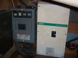 A modified wave inverter is less expensive, but can exhibit problems running some electronics, electric motors, and cordless tool or cell phone chargers. A true sine-wave inverter will avoid these problems. A capacity of 1800 watts should provide plenty of a/c power for this small building, and we can add another inverter when we transition to the main house. The inverter fed a second Square D 100 amp breaker box, from which all a/c circuits emitted. I wanted a/c power in the “kitchen” to power a blender, crock pot, and various other kitchen aids. We wanted a/c in the entertainment corner to power stereo and tv hardware, although I retained the d/c components to use during the lean power winter months. 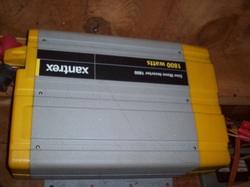 The entertainment corner, along with the home office circuit, was fitted with a surge protector strip for protection, as well as adding the ability to switch off all of the “phantom loads,” devices that use power even when turned off. The inverter draws about 2 amps when running, and this doesn’t seem like much, but adds up quickly in winter when generation is low. Doing without is not the objective! We now have a building wired in duplicate, one breaker box each for a/c and d/c circuits. Direct current powers all interior and exterior lighting, a ceiling fan, small refrigerator, stereo and tv, small fans for HVAC and the composting toilet, and numerous receptacles throughout the building. Alternating current powers a window air-conditioning unit, stereo and tv, the home office, and numerous receptacles. This arrangement could be very dangerous. What if we plug an a/c load into a d/c receptacle, or vice-versa? Something just blew up! The simple solution is to use keyed plugs and receptacles. Most standard 110 a/c plugs use two vertical spades, but plugs and receptacles are available with one vertical and one horizontal spade, which were used for d/c circuits. This must be done to adhere to code, but more importantly, is a no-brainer. We can’t mix up a/c and d/c circuits and appliances and have things blowing up! 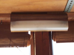 I began the lighting experiment by using recreational vehicle 12 inch florescent fixtures with F8T5 bulbs. They emit lots of light, but consume 1 amp when on and are not environmentally friendly. The high power consumption is not a problem during ten months of the year, but is too high for the period from Jan. 1st thru the middle of February. I began the process of converting to led fixtures and bulbs. We switched from florescent to Utilitech 61621 floodlight fixtures, available at Lowe’s for about eight bucks. 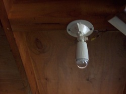 These fixtures are not fancy, but they get the job done for little cost. We then used an E27 1watt 12 volt 21 led white bulb, available at tmart.com for $5.25 each, half the price of the F8T5 bulbs, less toxic, and much longer life. We have strings of 12 volt led lights, obtained from Backwoods Solar Electric Systems, that have operated since 2003 trouble free, so we felt comfortable with led’s. We have had few problems with the new bulbs. These led bulbs are the trick. They supply plenty of light but consume only .15 amps. That’s less than 2 tenths of an amp. What this means is that we can run 6 led lights on the same amount of power as 1 florescent! We can turn on every light in the building and not be concerned about power usage, although that has become second nature by now. Offgrid living demands that one pay attention not only to weather forecasts, but power usage patterns as well. An unlimited budget would eliminate these concerns, but this entire experiment was designed to use as little cash as possible and still be “livable.” Oak Ridge National Laboratory has designed and built an ultra efficient, some call “net zero,“ home that is “energy neutral.” It supplies all of it’s own energy needs. The trouble is, the budget needed to construct this home is out of reach for most of us. For this technique to be useful, it must remain realistic, cost wise. The foremost goal of this experiment was to live without monthly bills of several hundred dollars or more, with some level of comfort, and not need a $100,000.00 budget to do it.  Our ceiling fan is 12 volt, reversible, uses 1/10th of an amp, and runs the vast majority of the time. It is a valuable aid in circulating fresh air in summer and distributing heat in winter. We plan to add a second one in the future.
If you have followed all of these articles since the beginning, it is clear that we are trying to build a rather conventional house using some unconventional methods, most of which have worked out extremely well. My wife has commented on numerous occasions that the power system has worked out best, by far, of any of the ideas that I’ve put into practice. I agree. Solar power has been the most important factor in our ability to conjure up a sustainable lifestyle. I am amazed that society as a whole has not embraced this wonderful technology. If a system is designed correctly, it will be as close to perfection as one can get. In future articles, I will detail such topics as heating and ventilation, rainwater harvesting, the home office, outdoor living spaces, and give details about the battery bank storage set-up. The best thing about this entire venture is that anyone can do it. I have no college degree, and when I began this mess (uh experiment), I had little specialized training. I suppose I got lucky, achieving such success on the first try. Plenty of research was the most beneficial tool that I started with. That, and the desire to reuse and recycle any and everything when possible. In memory of my “little brother” Jeffrey Allen Hurd, Rest In Peace All photos by: Jeff & Kathy Chaney Visit us at Natural Power & Light  After building and installing the array last time in “Power Us Up, Scotty”, we are ready to bring the power where we need it, inside the building. The “service entrance” (pictured in previous article) was located 6 feet from the northwest corner of the building, to place it underneath the first short flight of steps and landing. I had chosen to house the battery bank and peripheral equipment (to be detailed with photos in a future article) under the stairs because of limited space in this small building. This action did not conform to code, it did not allow ample room or access to the hardware. The biggest detriment was the fact that the stair treads must be removed to inspect and water the batteries. Very cumbersome. When the main house is built, I will include a “power room”. I installed a reducer at the building end of the underground pipe, to convert the 6 inch pipe to 2 ½ inch. The smaller pipe rose about 2 feet above ground, to enter the building. The joint between pipe and wall was caulked. 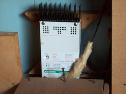 Having a limited budget at the time, I chose a Xantrex C-30, 30 amp charge controller. Consisting of two modules with a total output of 14.2 amps, the array would mate to the C-30 just fine, with room to expand later. The 1/0 (one ought) power lines were connected to a junction block. #6 wire was used for the short run from the junction block to a disconnect, from the disconnect to the C-30, then finally to the battery bank. I had decided to use a combination of batteries for head-to-head testing purposes. This is highly NOT recommended! Lower performance and battery life will result. In spite of this knowledge, I am known to conduct some unorthodox experiments. I used four Optima yellow top and four Deka marine 12 volt deep cycle batteries, all wired in parallel to maintain 12 volts and multiply storage amp/hours. The Optima’s contain gel electrolyte, the Deka’s flooded lead acid. These should not be used together, but I wanted to compare them. The main reason not to combine them is that they have different charging requirements. The best charge voltage for one type is not best for the other type. As a result, one type will suffer and not yield a full lifetime. As a compromise, I set the field adjustable bulk and float charge voltages as follows: bulk voltage - 14.4 volts, float voltage - 13.3. These voltages match the requirements for the lead acid batteries, but are not ideal for the gel cells. Even though my test was lacking some accuracy, the results were not unexpected. With 8 years of use, the lead acid batteries had to be replaced at 4 year intervals. The gel cell batteries were replaced at the end of the 8 year cycle, yielding twice the life of the lead acid type. At twice the initial cost, the gel cells lasted twice as long. The other main factors were that the gel cells did not have quite as many amp/hours of storage capacity, nor did they receive optimum charge voltages. On the plus side, they did not require watering. The final conclusion was that either type would do a fine job, and at a comparable cost. Large industrial batteries are available, and well suited, to this application. However, they come with two huge disadvantages. One, they are very heavy and require machinery (a forklift) to handle them, and shipping costs are high. Two, they represent a large initial expense. But, when you consider that they will last for up to twenty years, they can be very cost effective in some situations. 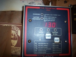 The next, but most important by far, component installed was a shunt from which the battery meter could monitor system performance. I chose a Trimetric 2020 meter from Bogart Engineering, shunt included, that is very simple to use and program. I consider this meter the absolute minimum monitoring device one should use. Other, more sophisticated meters are available that will log and store more data, if the budget allows. THE most critical exercise in offgrid living is battery bank health and state-of-charge, which must be tracked very closely. Meter cost is negligible compared to battery bank replacement expense. The shunt is wired into the negative main battery bank cable. All charge entering and all loads exiting the bank must route through this shunt to yield accurate results. In the early days, we viewed the meter thirty-plus times daily. Ten years later, it is still checked several times every day. The battery meter truly is your lifeline. Power was then run to a conventional Square D breaker box, whose breakers were d/c rated. This would be the “12 volt” or “d/c” breaker box. I wanted to utilize d/c throughout the building as much as possible, since d/c is more efficient than a/c, especially for loads having long run times. The Novacool refrigerator and all lighting would be d/c powered. From this breaker box, the building was wired with 12 volt d/c using standard 12/2 wire, as opposed to conventional 14/2, to minimize line loss. Standard switches and outlets were placed throughout the building. 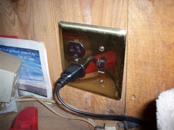 All outlets were switched, plus we utilized switched surge strips in the entertainment center and home office, to help eliminate “phantom loads”. Any appliance that uses a remote control draws power all the time, even when turned off. If it has a digital clock, it draws power continuously. These constant power draws quickly add up to a lot of unnecessary usage. Practically every building can realize reduced usage by at least 10% by eliminating “phantom loads”. Stereo systems, televisions, numerous clocks on myriad appliances, coffee makers, and anything that employs a timer, are “phantom loads”. A stereo will lose the preset stations, a small price to pay, but a t.v seems unaffected. Future articles will examine this in detail.
We have power to spare in the summer months, but in winter need to save all the power we can to avoid generator use. What we can not avoid is to reuse and recycle any and everything when possible. All photos by Jeff & Kathy Chaney Visit us at: Natural Power & Light 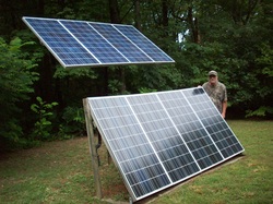 After getting this building in the shell last time in Enough Rest, Onward Ho, it is now time to think about having what “Tim Taylor” always wanted, more power! We currently have one 130 watt solar module charging two automotive batteries, not the ideal arrangement. We have a car stereo, a 13 inch tv, and a toilet fan. We desperately need lighting. Natural light entering from the plexiglass at the top of the exterior walls is plentiful during the day, but at night we need some help. I am spending more time at the property as conditions improve. Also, all work thus far has been achieved by use of cordless tools, so charging capabilities would be very handy. It was time to add to the solar “array.” I decided to use a pole mount for the array since I could save money by building it myself, and I had most of the material on hand. The previous winter, I had chosen the exact location for the mount and drove a stake in the ground to mark it. Starting around December 15th, I began looking for a clear day, as close to the solstice as possible. On the 18th, the sky was clear so I noted the exact time of sunrise and sunset on that spot, and divided the length of day by 2, to yield solar noon. Then, on December 21st at solar noon for that spot, I aligned another stake behind, and in the shadow of, the first stake. I now had the orientation of the array. Actually, a variation of 15 degrees east or west will be of little consequence. In hindsight, and for the main house, 15 - 20 degrees west of true will provide greater generation because the sun is slightly stronger a little later in the afternoon. A 2 ½ foot deep hole was dug to accept the pole, then filled with concrete. This arrangement has worked trouble free for ten years. If the mount is located in an open area not in the forest, the hole would need to be larger and deeper, to withstand wind loading. In the state of Tennessee in 2003, the local power distributor required the electrical system inspection by a state licensed inspector. Not being connected to the local distributor, i.e. offgrid, an electrical inspection was not required. I’m “off the hook,” right? WRONG! Do not, I repeat do not, think you can ignore electrical code. As I’ve stated previously, you do not want to spend the cash and labor to build a power system only to have your building burn to the ground. Sustainable, remember? Code details are safety details. Bearing this in mind, I began construction of the power system. 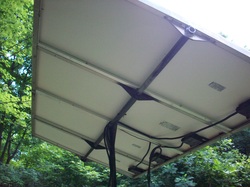 I built a frame to accommodate four 130 watt modules out of 1 inch aluminum angle, with gussets on the backside. I used 1 ¼ inch square tube steel for the pole. A length of round steel pipe, with gussets welded on, was attached perpendicular to the pole at the top of it. I inserted an aluminum tube, the length of the module frame, through the steel pipe at the pole top, and through the frame gussets, then welded the aluminum pole to the aluminum gussets. The module frame would then rotate in the pole mount. I researched the optimum seasonal tilt angles for the array (latitude for spring and fall, + or - 15 degrees for summer and winter), then positioned the array at these angles and drilled three corresponding holes through both pipes, on either side of the pole. I could then use a pin and clip in these holes to seasonally adjust the array for maximum output. Manual, but quick and easy. 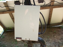 I next mounted an Outback Power combiner box on the pole. The modules were wired individually through 15 amp circuit breakers, even though each module output rating was only 7.1 amps. I used one breaker per module in anticipation of expanding the array in the future. The 15 amp breakers would allow this expansion, with extra capacity as required by code. All ampacity ratings must be exceeded by a minimum of 10%. (A little more would be better, as I would later learn, and will discuss in a future article.) An extra breaker was installed to accommodate a small gas generator. A surge protection device was installed in the combiner to complete array construction. 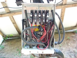 Located in fairly thick forest, the optimum location for the array was about 90 feet from the building, not the best of circumstances. D/C power does not travel distances well, being susceptible to line losses due to resistance. To keep line loss to a minimum, I had to use 1/0 (one ought) welding cable to transport electricity from the array to the building. In 2003, I purchased 400 feet of this cable at a cost of $500. Today, the cost would be much higher. The design needs to place the array as close to the battery bank as possible, to minimize losses and expense.
I now had to run the 1/0 cable “power lines“ to the building. Not wishing to deal with ice and fallen trees damaging the lines, I decided to run them underground. Since I had other excavation work to do, I rented a backhoe and dug a trench 2 feet deep, between the array and building. In the trench I placed a 1 inch layer of gravel, then 6 inch pvc pipe (to be discussed later), another 1 inch gravel layer, and finally a 4 inch pvc pipe to contain the power lines. The pole mount exit of the power line pipe, with cables protruding, was filled with expanding foam to keep out any critters. To assure a good ground connection through the adjustable pole mount, I attached a #6 bare ground wire between the array frame and the pole, which I allowed to ground itself. A better idea, and to adhere strictly to code, a ground rod should have been installed at the pole mount, and a separate conductor included in the pipe to bond to a second ground rod installed at the entrance to the building. Although I have had no problems thus far with my installation, I will do this properly next time. This was just a storage building, right? I keep referring to this, and will explain later. Even a storage building must be done correctly. For now, please reuse and recycle any and everything when possible. All photos by Jeff & Kathy Chaney Visit us at: Natural Power & Light (This article is dedicated to my friend Scotty McGregor of Brunswick, Ga., who saved my life more than once and helped me maintain my sanity during a long, hot summer in the Persian Gulf in 1981. Rock on Bruce - Les)  After finally getting this building under roof last time in Put The Lid On This Box, I discovered I had left out one very important detail. Getting older and dealing with Alzheimer’s is no fun, ha! The Ondura roofing material I used was supplied with ring-shank nails for installation. I decided to use screws around the perimeter of the sheets, the nails for the interior of the sheets. In our area, we had experienced higher than normal winds in recent years. Lots of friends and family had shingles blowing loose or completely off, so I figured perimeter screws would minimize this problem. To date, I have had none of these troubles. I’m not sure what wind load rating this method yields, but I like it. We now moved on to the gable ends. I started with the loft floor gable end, since it would be the easiest to position. This wall would take the form of a large triangle, so for ease of installation, I constructed it in two triangle sections. Of the eight windows I had purchased before construction began, I still had the two best ones. Since they were of quality, double pane design, I thought they would save the most energy by using them in the loft. Costing only $5 each, I was seeking maximum benefit. They were placed side by side in the center of the gable end wall. I assembled the two triangle sections on the loft floor, then stood them up into position, made sure they were plumb, then bolted them together and into place. One down, one to go. The front gable end was more difficult to deal with because of the cathedral ceiling in the front of the building. I purchased two decent quality double pane windows from Lowe’s, similar to the other two loft windows, then proceeded to build the two triangle wall sections on the main floor. Now I needed help. I recruited three friends to assist, then we heaved the first triangle section (half wall) into position. When it was secured, we went up with the second half. Everything fit pretty well, I had to lightly hammer the second section into place, a snug fit. This exercise was slightly dangerous, working from scaffolding. Safety must come first at all times! 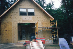 When I built the ground floor front walls, a hole was left in the center of the entire wall to accommodate an eight foot sliding glass patio door. The existing view was in this direction, so a patio door seemed appropriate. I built the door header extra beefy for ample support. After the gable end wall was in place above it, I installed the patio door. Utilizing the “bible,“ this step was a piece of cake. The shell of the building is now complete. I pondered whether to apply a house wrap at this time, but decided against it because this is a storage building, after all. I did not intend to “live” in it beyond completion since there would be no room, and disassembly would need to be as simple as possible. This was not a house, yet. 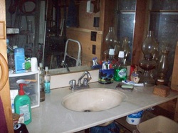 As I continued to work on the acreage to prepare a homesite across the road, I wanted to make the storage building as comfortable as possible. I also thought that this would be a perfect opportunity to test some ideas I had for the permanent house. The “cooler box” was a resounding success, as was the wood stove and kitchen stove (uh, grill). This approach developed in to a vicious cycle! I decided to locate a “bathroom” next to the cooler box. My builder friend had given me a four foot wide sink with matching mirror that had been removed from a motel room remodel. I installed the sink against the cooler box wall, then created a recess for it by placing a wall even with the sink front, extending toward the center of the building. 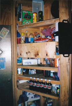 This action resulted in a recess for the “bathroom” sink, allowed for shelves on the sink side, and made room for some pantry shelves on the opposite side next to the cooler box door. I purchased a neo-angle (5 sided) shower stall, then installed it in the northwest corner of the bath. In the northeast corner, I installed a composting toilet. All of my research indicated that this particular toilet, a SunMar Excell non-electric model, should be ideal for the experiment at hand. It was also the least expensive. I included a 4 inch muffin fan in the vent pipe to eliminate any odors. This fan only draws one tenth of an amp, 12 volt d/c, so I could let it run 24/7 with no problems. Now having “facilities” was absolutely wonderful! The bathroom interior wall, as well as the kitchen interior wall, were left un-insulated and unfinished, the stud cavities to be used for storage shelves. In this small building, storage room was at a premium. 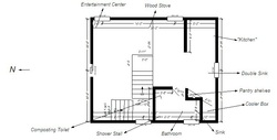 After describing all of the interior wall and stairway placements in the last few articles, I’m sure you are thoroughly confused by now. To help remedy this, I have included a floor plan drawing to clarify the details. Not being a professional writer, accurate descriptions are quite difficult. There may also be items in the floor plan that have not been discussed, yet. (That darned Alzheimer’s!) But, one thing I always remember is to reuse and recycle any and everything, when possible.
All photos by Jeff & Kathy Chaney Visit us at: Natural Power & Light , Mother Earth News , & Facebook  After making lots of headway last time in Enough Thinking, Back To Work, we are about to get ahead of ourselves. While sitting and looking around, I noticed a future problem. The tops of the walls were not even with the loft floor. I would need to cut and install a double header to run the front half of the side walls and across the front wall, to create an even surface all the way around for the rafters to sit on. I was glad I spotted this before the tarp and plastic were removed, otherwise I would have had to scramble to devise a solution, with everything uncovered. While studying this dilemma, I realized that I had not anchored the loft floor to the walls. In years past, houses were just placed on top of foundations, particularly above basement walls. I can remember when I was a kid, a car hit a house and knocked it askew of the basement walls. This possibility could not be tolerated. I had bolted the main floor to the footers, and the wall sections to one another, so I needed to continue the philosophy with the rest of the building. The solution was to cut 20 pieces of 2 inch angle iron, 6 inches long, with holes drilled one inch from the ends in both surfaces. I would affix these with two bolts down through the top plate of the wall, and two bolts through the headers. An angle plate was placed at the ends and middle of each 12 foot section of side wall, and at the ends and one-quarter distance on the front and rear walls. Now, everything is nicely bolted together, plus we have a uniform surface on which our rafters will sit. All we need now is a stretch of dry weather. After waiting for a couple of weeks, the weather forecast finally came out that called for no rain or snow for the next week. This was the window I had been waiting for. The walls were ready, the rafters were cut, and everything was waiting on my decision. I made the call, and removed the coverings. Ready or not, here we went. 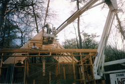 My wife had a couple days off from work, so I decided we would attach the first two rafters to the ridge beam and stand up the assembly on the loft floor. I had previously cut a brace to bolt to the end of the loft floor, to support the other end of the ridge beam. With the two rafters fastened to the ridge beam, we attempted to raise the assembly and place the brace. Bad idea! We did not have enough muscle. We were in the middle of the operation and could not go on up, or come back down, with the assembly without someone getting hurt. We were stuck. At that very moment, I heard a truck coming down the mountain that I recognized as a lifelong friend of ours, Louis Smith, now deceased, arriving in the nick of time, to help us get the mess in place. We were never as glad to see anyone as then! Next, I called my previous employer, Rental Service Corp. (RSC), to arrange to rent a 40 foot articulating boom lift to install the remaining rafters. I used hurricane brackets to fasten the rafters to the loft floor, wall headers, and ridge beam, installing 10 screws per bracket. This seemed sturdy enough to me. Installation of the remaining rafters was completed without incident. Now we needed plywood, and it up on the rafters. I decided to use the boom lift for this operation. We could have used ropes to lift the plywood into place, but I had saved lots of money thus far, and now seemed the time to splurge a little. One detail I need to mention is that I used a plumb-bob, hanging from the ridge beam over the front wall, to center the roof on the building. In the past, I had observed roofs that were not plumb with the building, causing myriads of alignment problems later on. 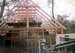 With the roof decking down, we applied a layer of 15 pound felt. The decision was at hand about what type of roofing material to use.
After lots of research, I chose a product named Ondura, purchased at Lowe’s. This roofing would be conducive to our plan to harvest rainwater, and was guaranteed for the life of the building when used in a non-commercial application. Also, by using this product, we would avoid the difficulty of having to filter out the pebbles that invariably detach from asphalt shingles, and would avoid the heating and painting associated with a metal roof. I despise painting! We installed vented seals under the upper and lowers edges of the Ondura to let the roof “breathe”. I now decided to splurge even more by hiring some help. The roofing would be difficult to install on a 12/12 pitch, a 45 degree angle. I did not wish to use toe boards, so we used a climber’s harness attached to trees on either side of the building, that had supported the large tarp in the beginning. Paying two helpers quickly depleted the budget, but I had saved on everything thus far, to compensate for the expense. To finish this phase, I had a company install aluminum gutters with round outlets, practically level. This was needed to accommodate my roof wash down system, before collection of rainwater begins. The gutter guy commented that this building was as square as any he had seen, one-quarter inch off. He said some he had dealt with were as much as a foot out of square! Finally, we are now “in the dry!” After busting hump for two weeks, we could take a well deserved breather. There were a million things to think about and plan, but physical work could slow, except to reuse and recycle any and everything when possible. All photos by: Jeff & Kathy Chaney Visit us at: Natural Power & Light , Facebook , & Mother Earth News  After all of the mental exercise in the last article A Plan Comes Together, it is time to get back to work. Winter is whizzing by, and I had to be ready when spring arrived to uncover this mess and erect the permanent roof. The starter solar power system I had installed was working flawlessly, which allowed the long winter to pass relatively quickly. During this time, I assembled the front half of the side walls, then pre-cut all of the rafters and collar ties, to be ready to go in spring when the weather broke. I also pre-cut stringers for the stairway, since the first thing I would need to begin the roof would be access to the loft floor. If, and when, a dry spell arrived and the cover was removed, roof construction had to move swiftly and seamlessly. I thought about this operation constantly, and prayed very hard that all of my calculations were correct! If not, I would have a “mell of a hess” on my hands. 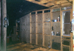 At one point in the middle of all this commotion, a few days of clear, dry weather appeared. I decided to raise the front of the plastic off the floor and install the front side walls. As it turned out, the break in weather was only long enough to erect one side wall, which dictated that I re-cover with the plastic, then wait for a second opportunity to do the other side. In about a week, the weather window opened and allowed the installation of the other front side wall. The hard part of this operation was not erecting the walls, but trying to re-cover everything for protection. 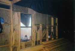 Now, with the side walls completed, I concentrated on the floor plan again. I decided to go in the rear east corner and create a “kitchen.” I built a wall six feet long and installed it six feet from, and parallel to, the rear wall, attached to the east wall. I then covered the front of this wall with 1x pine planks that were sawed from the property. I left the “kitchen” side bare and used the cavities in the framing for storage. This arrangement proved very handy, and is still in use today. The picture of the kitchen corner shows the top of the propane grill I used as a cooking stove. After almost killing myself previously, I made sure to open a window when it was in use. Ventilation is paramount! 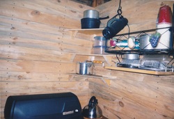 In the rear wall, centered underneath the double windows, I installed a double bowl kitchen sink, using 5/8 inch plywood with two coats of polyurethane as a countertop. My builder friend supplied the ceramic splash block, at no charge. I had previously installed the drain for the sink. We now have a functional “kitchen". Next, I moved to the problem of refrigeration. I decided to locate the fridge on the opposite side of the building from the “kitchen stove.” Being only 20 feet wide, this was not a great distance, but made more sense than putting it right beside the stove. The southwest corner was least desirable, and the “cooler box” and stove should have been switched. I plan to swap their locations in the final plan across the road. A lesson learned!  So, in the rear western corner, I built a wall four feet long and positioned it forty inches from, and parallel to, the rear wall, attached to the west wall. An interior door was installed, the cool side insulated with ½ inch closed cell foam having a 4.2 R-value. Plans were to double the foam in the future. The six inch wall cavities were filled with the same foam board cut to fit, then R-19 faced fiberglass was used on top of the foam, yielding a 23.2 total R-value. A length of pipe insulation was cut lengthwise and affixed to the bottom of the door to serve as a threshold seal. We now have a “cooler box”.
What appliance do we need to use? Because of the high run time, I chose an ultra-efficient 12 volt Novacool 4.3 cubic foot model, purchased from Backwoods Solar Electric Systems. When it arrived, I perused the instructions, which discussed adding extra insulation. What a novel idea! I had never thought about that. As per the “dummy sheet,” I removed the screws attaching the condenser coil, to loosen it and pull it away from the rear of the box just enough to add 3 inches of extra foam insulation. There was not room for more. The compressor chassis was loosened, to install 2 inches of foam around it. The top, bottom, and sides got 6 inches added, with 3 inches applied to the door. I was amazed at how easy the operation was, and this can be done to any fridge. In the future, I will do this to any refrigerator I use! I next built a shelf inside the box, on which to set the fridge. The shelf was located thirty-seven inches off the floor, spanned the width of the entire cooler box, depth matching the fridge. The extra-insulated fridge was placed on the shelf with the rear against the west wall, the left side against the south wall. Before placement, I cut rectangular holes in the west wall at the fridge’s rear, then installed foundation vents upside down on the exterior wall. This would allow the compressor section to vent heat to the outside, and prevent heat build-up inside the cooler box. After the fridge was placed on the shelf, the left front side, right rear side, and top were caulked to block compressor heat from entering the box. The fridge door was configured to open from right to left. Lastly, I inserted a one-and-one half inch pvc pipe into the rear wall, as high as possible, to serve as a vent for the entire box. A valve was included in the pipe, inside the cooler box, to open and close with the seasons. In summer, the valve remains closed. In winter, the valve is opened to allow cool air in. This uses outside air to keep the box at minimum temperature. Finally, after all this planning and work, we have an ultra-efficient refrigeration capability. The set-up has resulted in a fridge run-time, or duty cycle, of about 20%. Using 12 volts, and only running 20% of the time, the resulting electrical need has been minimal. Everything still works as well as the day of installation, requiring no maintenance or repairs to date, which has left plenty of time to reuse and recycle any and everything! All photos by Jeff & Kathy Chaney Visit us at: Natural Power & Light , Mother Earth News , & Facebook  After almost dying from asphyxiation, then settling in for the winter in the last article Time To Batten Down The Hatches, I felt pretty good about my chances of being around to actually see spring arrive. It was the end of November by now, and it never dawned on me that I would be living in a 12 x 20 foot room for at least the next three months. I was too busy with everything else at the time to think about that. Being alone for an extended span would allow the creative thought process juices to really flow. I had to come up with a plan, a floor plan, that is. As discussed in early articles, I did not have a large retirement account to fall back on in later years. A better idea to me was to try to set up a lifestyle and home that would not cost a fortune to maintain. Not having a lot of money would not be a bad thing if I didn’t need a lot of money. What a concept! I intensely disliked the amount of “typical” monthly bills that everyone just assumes are part of life. So, how abnormal would we have to become to minimize or eliminate “monthly bills”? As it turned out, not very. After a massive amount of pondering, I decided to stray from the conventional technique of laying out a house floor plan. Certain things had just always been done a certain way, and the question I had was, why? Some things made no sense to me. I then set out to turn conventional thinking on it’s ear. Before starting this fiasco, uh project, I wanted to use a 12/12 pitch roof, a 45 degree angle, which is very effective at shedding debris, rain, and snow. The steep slope would lessen the likelihood of leaks, as well as facilitate the ventilation and heat distribution ideas I had for the interior. The first, and I think most groundbreaking, epiphany involved the kitchen cooking stove and the refrigerator. The cook stove is the second largest heat source in the home. What sense does it make to place the refrigerator immediately adjacent to, or very near, a large heat source? The operation of one is quite detrimental to the other, creating inefficiency and higher operating costs for both. There had to be a better way. I decided to construct a “cooler box” on the opposite side of the kitchen from the cook stove. This “cooler box” would be a room, 4 x 6 feet, heavily insulated, with a door. The fridge would go inside, and this room would help insulate it from the heat of the building, especially in winter. I could weatherstrip the door threshold, then run a pvc vent pipe to the outside to flood the “cooler box” with cold air during the winter. A valve would close the vent in summer. All of this should minimize fridge run time year-round. The “cooler box” would also serve as a root cellar. The southwest corner of the building would not be the optimum location for this room, but the arrangement surely would work better than the standard. We will cover all the details of “cooler box” construction and refrigerator installation at the appropriate time. Up to this point, my toilet facilities had consisted of the use of backcountry camping regulations. Sewer lines were not available, and a septic system would be costly. More importantly, lots of trees would have to be removed to accommodate the drain field lines. I made the decision to test the effectiveness of a composting toilet. I had also installed a “grey water” drain for the kitchen and bathroom sinks, and shower stall. I will cover this step later in great detail. I was unaware at this stage that hugely unforeseen problems would need to be dealt with. My thoughts now turned to heating and ventilation. I would heat the building with a wood stove, since I could not walk on the property without tripping on firewood! But, the aforementioned chalet style roof, in tandem with the half loft and half cathedral ceiling, created difficulty with heat distribution. The loft would be very warm year-round, but the heat would be needed down on the main floor during heating season, and expelled during summer. A low cost, but very effective, solution came to mind. What about water? There have been news reports lately about a community nearby that is having technical difficulties with their water system. Residents have been without water for a week, and are getting desperate. There were no “city” water lines present at my location, plus I didn’t relish having to pay the monthly bill, which would surely increase with time. I had used a deep well before, with great success, but the problem here is that a well is an unknown cost that one can not begin to estimate. In previous years, within a mile of my property, one well went 128 feet deep, mine was 329 feet, and another was over 700 feet. All three wells were within a mile of one another. This cost could range from around $5000 up to $20,000, or much more. Then, it hit me like a ton of bricks! Why all the worry about obtaining something that falls from the sky for free? “Manna from heaven!” I love it when a plan comes together. A roofing material compatible with this approach would be needed. Standard asphalt shingles would be troublesome, due to the “pebbles” that dislodge from them over time. These could be filtered out, but added maintenance was a detriment. Metal roofing was unattractive because it would contribute to heating in summer. After some research, I stumbled across a beautiful solution, to be explained later. The water holding tank technique would play right into my hands. I could install a tank to accommodate cold water downstairs, and a second, larger tank located on top of the collar ties that connect opposing rafters above the loft floor upstairs, for hot water. The upper tank would be in the warmest part of the building, and be very easy to mate with a solar water heating system. Water pressure would be lowest from the lower tank, but according to my calculations, sufficient for my needs. I have had some good ideas, but will they work in practice? The great engineer’s question. Just because it looks good on paper doesn’t necessarily mean it will work. Next time, we will start finding out if, and how well, they suffice. My brain is tired after all this thinking, but one can not forget to reuse and recycle any and everything, when possible. Visit us at: Natural Power & Light , Mother Earth News , & Facebook |
AuthorThe Chaneys have lived off-grid for fifteen years, built a homestead themselves, and advise on related matters. This is the story of their adventure.. Archives
March 2017
Categories  
 |
Off the Grid
 RSS Feed
